Fleming's Left Hand Rule

 Fleming's Left-Hand Rule

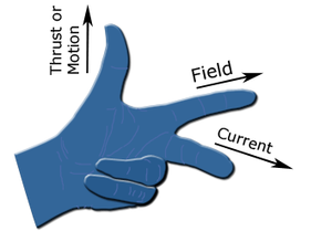
Fleming's Left-Hand Rule is used to determine the direction of force acting on a current-carrying conductor placed in a magnetic field. According to this rule, if the middle finger, forefinger, and thumb of the left hand are at right angles to one another and if the middle finger and forefinger represent the direction of current and magnetic field respectively, then the thumb will indicate the direction of force acting on the conductor.

Fleming's Left-Hand Rule
Image Source - Wikipedia


The rule is used to determine the direction of motion of a conductor (rotor) in the magnetic field produced by the stator for a motor.

Watch Video-

Share:

30+ MCQ on DC Basics and Network for Electrical Engineering

Multiple Choice Questions (MCQ) on DC Basics and Network for Electrical Engineering

In this article, we are providing you MCQ on DC Basics and Network for Electrical Engineering.

1 - In gases, the flow of current is due to
(a) electrons only.
(b) positive and negative ions.
(c) electrons and positive ions.
(d) electrons, positive ions, and negative ions.

Ans = d

MCQ on DC Basics and Network for Electrical Engineering
2. The minimum requirements for causing a flow of current are
(a) a voltage source, a resistor, and a switch.
(b) a voltage source and a conductor.
(c) a power source and a bulb.
(d) a voltage source, a conductor, an ammeter, and a switch.

Ans = b

3. Current velocity through a copper conductor is
(a) nearly 3 x 10^9 m/s.
(b) of the order of a few micro m/s.
(c) independent of current strength.
(d) the same as the propagation velocity of electric energy.

Ans = b

4. The drift velocity of electrons is
(a) larger than the speed of light.
(b) almost equal to the speed of light.
(c) equal to the speed of light.
(d) very small in comparison to the speed of light.

Ans = d


5. The condition for the validity of Ohm's law is that the
(a) temperature should remain constant.
(b) current should be proportional to voltage.
(c) Resistance should be wire wound type.
(d) all of the above.

Ans = a

6. Two wires A and B of the same material and length l and 2l have radius r and 2r respectively. the ratio of their specific resistance will be
(a)1:1
(b)1:2
(c)1:4
(d)1:8

Ans = a

Best MCQ Book on Electrical Engineering = Click Here

7. The electrical conductivity of metals is typical of the order of (In 1/ohm-m)
(a)10^7
(b)10^5
(c)10^-4
(d)10^-6

Ans = a

8. Resistance of a copper wire always increases if
(a) temperature is reduced.
(b) temperature is increased.
(c) the number of free electrons available becomes less.
(d)the number of free electrons available becomes more.

Ans = b/c


9. Pure metals generally have
(a) high conductivity and low-temperature coefficient.
(b) high conductivity and large-temperature coefficient.
(c) low conductivity and zero temperature coefficient.
(d) low conductivity and high-temperature coefficient.

Ans = b

10. The temperature coefficient of resistance of a wire is 0.0008 °C, and the resistance of the wire is 8 ohm at 0°C, what is the resistance at 100°C?
(a) 8.64 Ohm.
(b) 8.08 Ohm.
(c) 7.92 Ohm.
(d) 7.20 Ohm.

Ans = a

11. If the length of a wire of resistance R is uniformly stretched to n times its original value, its new resistance is
(a) nR
(b) R/n
(c)n^2R
(d)R/n^2

n^2 = n square

Ans = c

12. The hot resistance of the filament of a bulb is higher than the cold resistance because the temperature coefficient of the filament is
(a) negative
(b) infinite
(c) zero
(d) positive

Ans = d


13. temperature coefficient of resistance of an insulator is
(a) positive and independent of temperature.
(b) negative and independent of temperature.
(c) negative and dependent on temperature.
(d) positive and dependent on temperature.

Ans = c

14. Four resistances 80 ohms,50 ohms,25 ohms, and R ohms are connected in parallel. Current through 25 ohms resistance is 4 A. The total current of the supply is 10 A. The value of R will be
(a) 66.66 ohm
(b) 40.25 ohm
(c) 36.36 ohm
(d) 76.56 ohm

Ans = c

15. Three parallel resistive branches are connected across a dc supply. What will be the ratio of the branch currents I1 :I2: I3, if the branch resistances are in the ratio R1: R2: R3:: 2: 4: 6?
(a) 3:2:6
(b) 2:4:6
(c) 6:3:2
(d) 6:2:4

Ans = c

16. The flow of electric current in a conductor is due to the flow of
(a) electrons
(b) protons
(c) electrons and ions
(d) charged particles

Ans = a

17.  An electric current is the
(a) the random movement of electrons in a conductor
(b) movement of free electrons predominately in one direction
(c) the pressure difference between two poles
(d) the power that causes drifts of electrons

Ans = b

18. How are 500-ohm resisters connected so as to give an effective resistance of 750 ohm?
(a) three resistors of 500 ohms each, in parallel
(b) three resistors of 500 ohms each, in series
(c) two resistors of 500 ohms each, in parallel
(d) two resistors of 500 ohms each, in parallel, and the combination in series with another 500-ohm resister.

Ans = d

19. When an electric current flows through a conductor, its temperature rises. This is because of
(a) mutual collisions between metal atoms.
(b) mutual collisions between conducting elections.
(c) collisions between conduction electrons and atoms.
(d) release of conduction electrons from parent atoms.

Ans = c

20. Two heaters, rated at 1000 W, 250 V each are connected in series across a 250 V, 50 Hz ac mains. The total power drawn from the supply would be _____W.
(a) 1,000
(b) 500
(c) 250
(d) 2,000

Ans = b

21. Four 100 W bulbs are connected in parallel across a 200 V supply line. If one bulb gets fused
(a) no bulb will light.
(b) all four bulbs will light.
(c) rest of the three bulbs will light.
(d) none of the above.

Ans = c

22. A 200 W, 230 V lamp is connected across a 115 V supply. The lamp will draw power
(a) slightly more than 50 W.
(b) slightly less than 50 W.
(c) exactly 100 W.
(d) exactly 50 W.

Ans = a

23. Two incandescent light bulbs of 40 W and 60 W ratings are connected in series across the mains. Then
(a) the bulbs together consume 100 W.
(b) the bulbs together consume 50 W.
(c) the 60 W bulb glows brighter.
(d) the 40 W bulb glows brighter.

Ans = d

24. A 100-watt light bulb burns on an average of 10 hours a day for one week. The Weekly consumption of energy will be ___unit/s.
(a) 7
(b) 70
(c) 0.7
(d) 0.07

Ans = a

25. Which of the following statements is incorrect?
(a) Resistance is a passive element.
(b) Inductor is a passive element.
(c) Current source is a passive element.
(d) Voltage source is an active element.

Ans = c

26. The terminals across the source are ____ if a current source is to be neglected.
(a) open-circuited
(b) short-circuited
(c) replaced by a capacitor
(d) replaced by a source resistance

Ans = a

27. Which of the following is an active element in a circuit?
(a) Current source.
(b) Resistance.
(c) Inductance.
(d) Capacitance.

Ans = a

28. Which of the following is not a bilateral element?
(a) Constant current source.
(b) Resistor.
(c) Inductor.
(d) Capacitor.

Ans = a

29. A circuit having the same properties in either direction is known as ____ circuit.
(a) bilateral
(c) irreversible
(b) unilateral
(d) reversible

Ans = a

30. The elements which are not capable of delivering energy on their own are known as
(a) unilateral elements.
(b) nonlinear elements.
(c) passive elements.
(d) active elements.

Ans = c

Read -
Share:

Megger | Definition and Working Principle

Megger | Definition and Working Principle

Megger Definition

Megger or Megaohm meter is an instrument that measures the insulation resistance of electric circuits relative to the earth and one another.
Meggar | Definition and Working Principle

Megger Working Principal

A Megger consists of an e.m.f. source and voltmeter. The scale of the voltmeter is calibrated in ohms (kilo-ohms or megohms, as the case may be). In measurements, the e.m.f. of the self-contained source must be equal to that of the source used in calibration.


Meggar | Definition and Working Principle
Above Image shows diagrammatically a Megger whose readings are independent of the speed of the self-contained generator. The moving system incorporates two coils 1 (current coil) and 2 (pressure coil) mounted on the same shaft and placed in the field of a permanent magnet (not shown) 90° apart. The generator energizes the two coils over separate wires. Connected in series with one coil is a fixed resistance R1 (or several different resistances in order to extend the range of the instrument). The unknown resistance Rx is connected in series with the other coil. The currents in the coils interact with the magnetic field and produce opposing torques.

Partner's SiteTurbotoplist

The deflection of the moving system depends on the ratio of the currents in the coils and is independent of the applied voltage. The unknown resistance is read directly from the scale of the instrument. (The accuracy of measurement is unaffected by variations in the speed of the generator between 60 and 180 r.p.m.).


You May Also Like-

Share:

What is Transformer? | Working Principle | EMF Equation

What is a Transformer? | Working Principle | EMF Equation

What is a Transformer?

A transformer may be defined as a static electrical device that transfers electrical energy from one circuit to another circuit at the same frequency but with changed voltage (or current or both) through a magnetic circuit.


What is a Transformer? | Working Principle | EMF Equation

Type of Transformer

Transformers are used in various fields such as power generation grid, distribution sector, transmission, and consumption of electric power.

There are several types of transformers that are classified based on the following factors:
  • Working voltage range
  • The medium used in the core.
  • Winding arrangement
  • Installation location

Based on voltage levels

The types of transformers in common use, according to the voltage, are classified as follows:
  • Step Up Transformer: They are used between the power generator and the electrical network. The secondary output voltage is higher than the input voltage.
  • Step Down Transformer – These transformers are used to convert the high-voltage primary supply to a low-voltage secondary output.

Based on the Medium of Core Used

In a transformer, we will find different types of cores that are used.
  • Air Core Transformer: The flux link between the primary and secondary winding is through the air. The coil or windings wound on the non-magnetic strip.
  • Iron Core Transformer – The windings are wound on multiple iron plates stacked together, providing a perfect link path to generate flux.

Based on the winding arrangement

  • Autotransformer: It will have a single winding wound on a laminated core. The primary and secondary share the same coil. Auto means "oneself" in the Greek language.

Based on the installation location

  • Power Transformer – Used in power generating stations as they are suitable for high voltage applications.
  • Distribution transformer: It is mainly used in distribution lines for domestic purposes. They are designed to carry low voltages. It is very easy to install and is characterized by low magnetic losses.
  • Instrument transformers: They are mainly used to measure voltage, current, and power.
  • Protection Transformers: They are used for the protection of components. In circuits, some components must be protected against voltage fluctuations, etc. The protection transformers ensure the protection of the components.

Working Principle of Transformer

When alternating voltage V1 is applied to the primary winding of a transformer a current (termed as exciting current, IΦ) flows through it. The exciting current produces an alternating flux (Φ) in the core, which links with both the winding (primary and secondary). According to Faraday's laws of electromagnetic induction, the flux will cause self-induced emf E1 in the primary and mutually induced emf E2 in the secondary winding. But according to Lenz's law primary induced emf will oppose the applied voltage and in magnitude, this primary induced emf is (almost) equal to the applied voltage. Therefore, in brief, we can say emf induced in the primary winding is equal and opposite to the applied voltage.
Working Principle of Transformer

When a load is connected to the secondary side, the current will start flowing in the secondary winding. The voltage induced in the secondary winding is responsible to deliver power to the load connected to it. In this way, power is transferred from one circuit (primary) to another (secondary) by winding through a magnetic circuit by electromagnetic induction. This is the working principle of the transformer. The induced emf in the secondary E2 is also in phase opposition to the applied voltage V1 at primary. if the secondary is open-circuited, terminal voltage V2 at the secondary is equal in magnitude and in phase with the induced emf at the secondary.

EMF Equation of Transformer

Since the applied voltage is sinusoidal at the primary, the flux produced by the exciting current is also sinusoidal.

If N1 be the primary number of turns, then the RMS values of induced voltage at primary is given by-

E1 = 4.44 Φmax f N1

(As the induced voltage in the primary winding is equal and opposite to the applied voltage, so V1 = 4.44 Φmax f N1 ).

Similarly, the RMS value of the induced emf at secondary is obtained as

E2 = 4.44 Φmaxf N2

Thus for a single-phase ideal transformer, the expressions for the induced voltages at the primary as well as at the secondary windings can be obtained from the above Eqns.


You May Also Like-

Share:

What is Moving Iron Instrument? Principal & Construction | Advantage & Disadvantage

Moving Iron Instrument

What is Moving Iron Instrument?

These instruments are sensibly exact, less expensive and simple in construction. These instruments are generally utilized in research laboratories and on electric boards. Moving iron instruments are normally utilized either as ammeters or voltmeters. Moving iron instruments are of two types:

  1. Attraction type
  2. Repulsion type
Moving Iron Instrument

Attraction Type Moving Iron Instruments

Principle - When an unmagnetized soft iron piece is placed in the magnetic field of a coil, the piece is attracted to the coil. The moving system of the instrument is attached to a soft iron piece and the operating current is passed through a coil placed adjacent to it. The operating current sets up a magnetic field that attracts the iron piece and thus creates deflecting torque in the pointer to move over the scale.

Construction - It consists of a hollow cylindrical coil (or solenoid) that is kept fixed. An oval-shaped soft iron piece is attached to the spindle in such a way that it can move in or out of the coil. The pointer is attached to the spindle so that it is deflected with the motion of the soft iron piece. The controlling torque on the moving system is usually provided by the spring control method while the damping is provided by air friction.

Working Principle - When the instrument is connected in the circuit, the operating current flows through the coil. This current sets up a magnetic field in the coil. The coil then behaves like a magnet and it attracts the soft iron piece towards it. The pointer attached to the moving system moves from zero position across the dial.
Attraction type Moving Iron Instruments

If the current in the coil is reversed, the direction of the magnetic field also reverses and so does the magnetism produced in the soft iron piece. Hence the direction of deflecting torque remains unchanged. Therefore, such instruments can be used both for dc as well as ac measurement of current and voltage.
The force F pulling the soft iron piece towards the coil depends upon
(i) The field strength H produced by the coil.
(ii) The pole strength M developed by the iron piece


Repulsion type Moving Iron Instruments

Principle - These instruments are based on the principle of repulsion between the two iron pieces magnetized with the same polarity.


Construction - Any Repulsion Instrument consists of a fixed cylindrical hollow coil that consists of the operating current. Inside the coil, there are two soft iron pieces of vanes, one of which is fixed and the other is movable. The fixed iron vane is attached to the coil whereas the movable vane is attached to the spindle. Under the action of deflection torque, the pointer attached to the spindle moves over the scale.

The controlling torque is produced by the spring control method and damping torque is provided by air friction damping in repulsion type instruments.

Working Principle - When the instrument is connected in a circuit and current is flowing through the circuit, the current sets up a magnetic field in the coil within the instrument. The magnetic field magnetizes both the iron vanes in the same direction (i.e. both pieces become magnets with the same polarity) they repel each other. Due to this force of repulsion, only movable iron vane can move as the other piece is fixed and cannot move. The result is that the pointer attached to the spindle moves from zero position.

If the current in the coil is reversed, the direction of deflection torque remains unchanged. This is because both iron vanes are in the same magnetic field and so they will be magnetized similarly and consequently repel each other irrespective of the direction of the magnetic field. Hence, such instruments can be used both for ac and dc measurements. The deflection torque is generated due to the repulsion between the similarly charged iron pieces.

Advantage and Disadvantage of Moving Iron Instruments

The moving iron instruments have the following advantages:
  • They are cheap. robust and simple in construction.
  • The instruments can be used for both ac as well as dc circuits.
  • These instruments have a high operating torque.
  • These instruments are reasonably accurate.

The following are the disadvantages of moving iron instruments:
  • These instruments have a non-uniform scale.
  • These instruments are less sensitive to changes in operating variables.
  • Errors are introduced due to the change in frequency in case of ac measurement.
  • The power consumption of these instruments is relatively higher.

Error in Moving Iron Instruments

(1) Errors due to Hysteresis
Since the iron parts move in the magnetic field, hysteresis loss occurs in them The effect of this error will result in higher readings when current increases than when it decreases. The hysteresis error can be eliminated by using "mumetal" or "permalloy" which have negligible hysteresis loss.

(ii) Error due to Stray Fields
Since the operating magnetic field is comparatively weak, therefore such instruments are susceptible to stray fields. This may give rise to wrong readings. This error is eliminated by shielding the instrument with an iron enclosure.

(iii) Error due to Temperature
Changes in temperature affect the circuit resistance of the coil and stiffness of the control springs.


You May Also Like -
Share:

Electric Field Intensity - Definition, Formula and Unit

Electric Field Intensity - Definition, Formula and Unit

In this post, we will cover the Electric Field Intensity Definition, Formula and Unit that will help you to understand Electric Field Intensity better.
Electric Field Intensity - Definition, Formula and Unit

Electric Field Intensity Definition-

Electric Field Intensity (E) may be defined in the following ways-

1. Electric field intensity is the force experienced by a unit positive charge placed at that point.

E = F/Q newton/coulomb (i.e., force per unit charge).

2. Electric field intensity is equal to the lines of force passing normally through a unit cross-section at that point.

E=Q/εA

3. Electric intensity at any point in an electric field is equal to the potential gradient at that point.

E = dV/dX volt/meter.

Electric Field Intensity Formula-

Electric field intensity Formula is given by-

E = F/Q newton/coulomb
or
E=Q/εA
or
E = dV/dX volt/metre


Electric Field Intensity Unit-

The Unit of Electric field intensity is newton/coulomb or volt/meter.


You May Also Like-
Share:

Coulomb's Law - Definition and Formula

Coulomb's Law - Definition and Formula

In this post, we will cover Coulomb's Law Definition and Coulomb's Law Formula that will help you to understand Coulomb's Law better.
Coulomb's Law - Definition and Formula

Coulomb's Law Definition-

The mechanical force produced between two magnetic poles is produced to the product of their pole strengths, and inversely proportional to the square of the distance between them.


Coulomb's Law Formula-

Coulomb's Law Formula
In the SI System, The law is given by-
where F is the force between the poles (in Newtons), m1 and m2 are pole strengths, d is the distance between the poles in meters, μ(r) is the relative permeability of the medium in which the poles are situated, and μ(o) is the permeability of free space (in air).

μ = Absolute permeability of air (or vacuum) x relative permeability μ(r).


Know More About Coulomb's law (Wikipedia)

Best Books For Electrical Engineering
  • Objective Electrical Technology By V.K.Mehta - Buy Now
  • An Integrated Course in Electrical Engineering By J.B. Gupta - Buy Now
  • An Integrated Course in Electrical Engineering By R.K. Rajput - Buy Now
You May Also Like-
Share:

Join Us on Telegram

Join Us on Telegram
Click on Image

Join Us On Facebook

Popular Posts

About

ElectricalNotes4u is a Blog for Electrical Engineering Students who want to learn Electrical Engineering online. We will Provide You Notes on all Major subject of electrical engineering. We also Provide Important MCQ that will help you to Prepare for Competitive Exam.